Among the different car manufacturers, vehicle models, and years, made before 1995 there are many different computerized engine control systems. Although there are significant differences between the various systems, when compared they are actually more alike than different.
COMMON FEATURES
Computers The comprehensive automotive computer is a small, highly reliable, solid-state digital computer protected inside a metal box. It receives information in the form of voltage signals from several sensors and other input sources. With this information, which the computer reads several thousand times per second, it can make decisions about engine calibration functions such as air/fuel mixture, spark timing, EGR application, and so forth.
These decisions appear as commands sent to the actuators the solenoids, relays, and motors that carry out the output commands of the computer. Commands usually amount to turning on or off an actuator. in most cases the ignition switch provides voltage to the actuators either directly or through a relay. The computer controls the actuator by using one of its internal solid-state switches (transistors) to ground the actuator’s circuit. In this way the transistor only has to deal with the low-voltage side of the circuit (the voltage is dropped and most of the
heat is produced in the actuator, outside computer).
No attempt should be made to open the computer’s metal housing. The housing protects the computer from static electricity. Opening it or removing any circuit boards from it in any other than carefully controlled laboratory con-ditions will likely result in damage to some of its components.
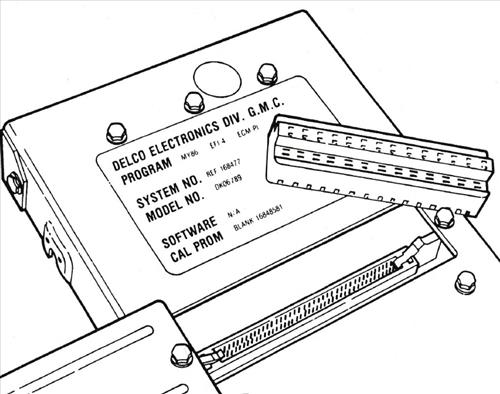
1989 General Motors electronic control module and PROM.
Location:
On most systems the computer s located inside the passenger compartment. This protects it from the harsh, high temperature environment in the engine compartment.
Engine Calibration.
Because of the wide range of vehicle sizes and weights, engine and transmission options, axle ratios, and so forth, and because many of the decisions the computer makes must be adjusted for those variables, the manufacturers use some type of an engine calibration unit.
The calibration unit is a chip that contains information that has to be specific to each vehicle. For example, the vehicle’s weight affects the load on the engine, so to optimize ignition timing, ignition timing calibration must be programmed for that vehicle’s weight. In a given model year, a manufacture might have more than a hundred different models counting different engine and options, but might use less than a dozen different computers.
This is made possible by using an engine calibration unit. The engine calibration unit may be referred to as the PROM, or some other term may be used. Some manufacturers make the calibration unit removable, and some make it a permanent part of the computer.
Five Volt Reference
With few exceptions all of the systems use 5 volts to operate their sensors. Within the electronics industry, 5 volts has been almost universally adopted as a standard for information transmitting circuits.
This voltage value is high enough to provide reliable transmission and low enough not to damage the tiny circuits in the computer.
Fuel Injection
There are two types of fuel injection systems used with comprehensive computerized engine control systems: single point and multi point They each use an intermittent or timed spray to control fuel quantity.
Single-point Injection. Single-point injection is often referred to as throttle body injection. Single point means that fuel is introduced into the engine from one location. This system uses an intake manifold similar to what would be used with a carbureted engine, but the carburetor is replaced with a throttle body unit. The throttle body unit contains one or two solenoid-operated injectors that spray fuel directly over the throttle blade (or blades). Fuel under pressure is supplied to the injector.
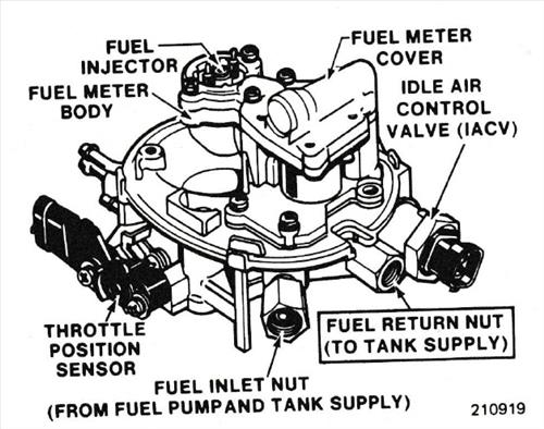
The throttle blade is controlled by the throttle linkage just as in a carburetor. The computer controls voltage pulses to the solenoid-operated injector, which opens and sprays fuel into the throttle bore. The amount of fuel introduced is controlled by the length of time the solenoid is energized. This is referred to as pulse width. The amount of air introduced is controlled by the opening of the throttle blade. The EFI system is characterized, especially on smaller engines, by excellent throttle response and good driveability.
Experience has shown, however, that the system is best suited for engines with small cross-sectional area manifold runners that at low speeds will keep the fuel mixture moving at a higher velocity. This reduces the tendency for the heavier fuel particles to fall out of the airstream. Multipoint Injection. Multipoint injection is often referred to as port injection and means that fuel is introduced into the engine from more than one location. This system uses an injector at each intake port. Fuel is sprayed directly into the port, just on the manifold side of the intake valve. The multipoint injection system provides the most advanced form of fuel control yet developed. It offers the following advantages:
• Spraying precisely the same amount of fuel directly into the intake port of each cylinder eliminates the unequal fuel distribution so inherent when already mixed air and fuel are passed through an intake manifold.
• Because there is no concern about condensing as it passes through the intake manifold, there is less need to r ea-the air or the manifold.
• Because there is no concern about molecules falling out of the airstream while moving through the manifold at low speeds, the cross-sectional area the manifold runners can be larger and thus offer better cylinder-filling at (volumetric efficiency, VE) at higher speeds.
• Most of the manifold-wetting process avoided; some wetting still occurs it port areas. If fuel is introduced into the intake manifold, some will remain or manifold floor and walls especially during cold engine operation and acceleration. Fuel metering has to allow for 7- fuel in order to avoid an overlean it cylinders. It has to be accounted for again during high-vacuum conditions because it will then begin to evaporate and go into the cylinders.
In general port fuel injection provides better engine performance and excellent drive-ability while maintaining or lowering exhaust emission levels and increasing fuel economy.
Fuel Pressure Regulators.
All fuel injector systems that are part of a comprehensive computerized engine control system use pulse width as the primary means of controlling fuel metering. A pressure regulator is used to provide a constant pressure to the injector electric fuel pump supplies under pressure to the regulator. The fuel pressure regulator is located on the fuel rail or manifold and allows excess to return to the tank.
A diaphragm spring pushes the diaphragm against fuel pressure. As the diaphragm moves in the direction the spring is pushing it, a flat disc in the center of the diaphragm closes off the fuel return passage. This allows less fuel to return to the tank and causes fuel pressure to go up, closer to fuel pump pressure. The increased fuel pressure moves the diaphragm against the spring. This allows more fuel to escape through the return line and thus causes fuel pressure to drop. The diaphragm will always find a balanced position that will keep fuel pressure at the desired value.
On some single-point injection systems, the spring side of the diaphragm is exposed to atmospheric pressure. Changes in atmospheric pressure produce a slight change in fuel pressure. Some multipoint injection systems connect manifold vacuum to the spring side of the diaphragm.
Changes in atmospheric pres-sure or in manifold pressure change the total pressure on the spring side of the diaphragm and therefore the fuel pressure. The intent, however, is not to increase or decrease fuel delivery but to maintain a constant pressure drop across the injector. For example, when manifold pressure goes up, the injector has to spray fuel into a higher pressure environment. In order for the correct amount of fuel to be delivered during the pulse width, fuel pressure must be increased in proportion to the manifold pressure increase.
Cars newer than 1995 are easier to troubleshoot thanks to OBD II computer connectors.